
Input characteristics: npn BJT (typical) The input characteristics look like the characteristics of a forward-biased diode.

Find the approximate values of bdc and adc from the graph.Output characteristics: npn BJT (typical) Note: The PE review text sometimes uses dc instead of dc. DC Models for a BJT:ĭC and DC = Common-emitter current gain = Common-base current gain = IC = IC IB IE The relationships between the two parameters are: = = + 1 1 - Note: and are sometimes referred to as dc and dc because the relationships being dealt with in the BJT are DC.


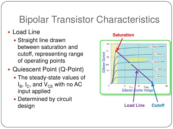
When analyzing a DC BJT circuit, the BJT is replaced by one of the DC circuit models shown below. (IE- 0) For CE Trans., IC = βIb + (1+β) Ico where β═α, 1- α is CE Gain Bulk-recombination current ICO Inc Ipe Ine Figure: An npn transistor with variable biasing sources (common-emitter configuration).Ĭommon-Emitter Circuit Diagram Collector-Current Curves VCE IC IC + _ Active Region VCC IB IB VCE Saturation Region Cutoff Region IB = 0īJT’s have three regions of operation: 1) Active - BJT acts like an amplifier (most common use) 2) Saturation - BJT acts like a short circuit 3) Cutoff - BJT acts like an open circuit BJT is used as a switch by switching between these two regions.
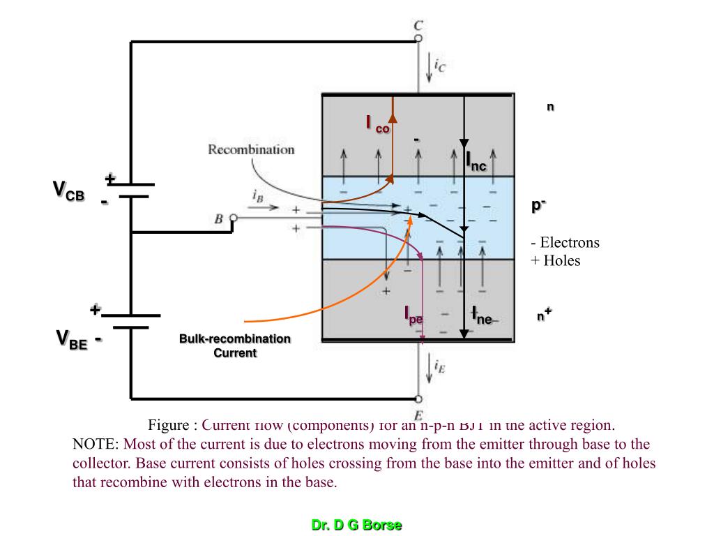
+ Holes B - + - + - p + + IB - VBE - _ įor CB Transistor IE= Ine+ Ipe Ic= Inc- Ico And Ic= - αIE + ICo CB Current Gain, α ═ (Ic- Ico). Carrier transport in the active base region directly beneath the heavily doped (n+) emitter dominates i-v characteristics of BJT. A small current also enters base terminal, crosses base-emitter junction and exits through emitter. Majority of current enters collector, crosses base region and exits through emitter. Consists of 3 alternate layers of n- and p-type semiconductor called emitter (E), base (B) and collector (C). Base current consists of holes crossing from the base into the emitter and of holes that recombine with electrons in the base. NOTE: Most of the current is due to electrons moving from the emitter through base to the collector. N I co - Inc + VCB - p- Electrons + Holes + Ipe Ine n+ VBE - Bulk-recombination Current Figure : Current flow (components) for an n-p-n BJT in the active region. Base doping is slightly higher ~ 1010 – 1011 īJT Current & Voltage - Equations IE IC IE IC - VCE + + VEC - E C E C - + + VBE VBC IB VEB VCB IB - + + B B n p n IE = IB + IC VCE = -VBC + VBE p n p IE = IB + IC VEC = VEB - VCB. The Two Types of BJT Transistors: npn pnp n p n p n p E C E C C C Cross Section Cross Section B B B B Schematic Symbol Schematic Symbol E E The BJT – Bipolar Junction Transistor Note: Normally Emitter layer is heavily doped, Base layer is lightly doped and Collector layer has Moderate doping. Bipolar Junction Transistor Basics C BJTs B E


 0 kommentar(er)
